(YAESU) SOMMERKAMP FT220 MODIFICATIONS
![]() 5 mar 2016. With TB76001
5 mar 2016. With TB76001
DESCRIPTION
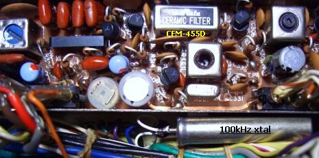
For SSB a 10.7 MHz crystal filter (300-2700 Hz ±3db) is used. A dual conversion is used for For FM; first IF is 10.7 MHz with a dual 10F30A crystal filter (XF301), then conversion to 455 kHz, followed by a 455 kHz (CFM455D) ceramic filter (CF301) of Murata. Those two FM filters are actually too wide for the current 12.5 kHz channel spacing.
PCB's are not all made of glass fiber-epoxy. Therefore, it is a tricky job to solder at the tracks because copper can be lifted when removing components.
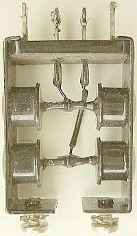
The scale drive is old-fashioned well made with 8 gears and a drum. The frequency reading on the circular linear scale is surprisingly good and an accuracy of about 500 Hz is possible.
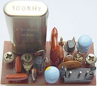
Calibration is possible with an internal 100kHz marker generator whose harmonics on 2 m are remarkably good to "receive". A relay temporarily disconnects the antenna. In practice the VFO is more stable than the 100 kHz oscillator!
That's because its location near the power transformer is not clever figured out. In operation the heated-up transformer is heating-up the relatively large 100 kHz crystal. Due to the increasing temperature the marker harmonics drifts up to 4 kHz! If the cabinet is removed, the oscillator stays stable and the scale can be calibrated pretty accurate.
I installed (fig») the crystal next to IF/FM PCB with extended wires, but it was not a real improvement. Better is a 6.4 MHz marker generator as outlined down this article. The calibrating points are then fairly accurate, which is an improvement of 64 times better than the original 100 kHz oscillator.
REPEATER
It is a pity that the repeater shift is different from present standard. By pressing RPT the receiving frequency is automatically shifted 600 kHz up. So, for repeater operation set the scale on the repeater input frequency and push the RPT button.
After studying the schematic, it seems possible to rectify by ordering a 63.1 MHz crystal and changing the wiring at relay RL2 (contact to "A" & "B") and switch RPT (S5a).
AC/DC SUPPLY
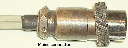
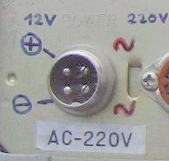
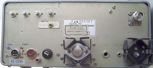
The plug for mains or external 13.8 V supply is a 4-pin microphone type («fig). With this curiously item and your mind elsewhere, one can easily change plugs.
With supply from the mains, voltage is approximately 14.5 V and RF power ouput is 12 - 13 W.
PRE AMPLIFIER
 The instruction manual statest: Sensitivity SSB 0.5 uV S/N 10 dB, FM -4 dB for 20 dB QS.
According to current standards, the receiver is a bit insensitive but DIY is possible. Comparison between an installed BF981 and the original 3SK40 (Q501) as input amplifier was not an improvement in terms of signal to noise ratio, only the gain of the first transistor was larger.
This can also be achieved with a cascade system by installing a J310 FET in series («fig) with 3SK40. Desolder 3SK40's drain and solder to J310's source. The latter is mounted self-supporting. See the schematic for more details.
After this modification and re-adjusting L501 and L503 of the cascode amplifier it improves reception of stations that previously were almost impossible to hear. Partly due to a slight change of the mixer, the current sensitivity is increased so that an FM signal of 0.1 microvolts is understandable and a 0.3 microvolts signal is virtually noise-free.
MIXER
Mixer Q502 (3SK40) appeared to improve if source resistance R510 («fig) was increased from 680 Ohm to 1.5 kOhm. That proved to be equal if this FET was replaced by a BF981, but the last increases the gain. If you do not need extra gain maintain 3SK40 in its original state.
For optimum result readjust L507 and L 508. Best is if you can use a spectrum analyzer for aligning helical filters L503, L504 and L507.
MARKER GENERATOR OR CALIBRATOR
In an on-site "CIRCUIT DIAGRAM" the marker generator is a 1 MHz oscillator followed by a divider and the PCB is numbered PB-1424.
However in three tested FT-220's a PB-1331A (fig») was installed. It is a 100 kHz crystal oscillator followed by a buffer/multiplier or pulse shaper. The change was later found in illegible diagrams on the Internet.
That is why I draw a schematic according to the actual components present on the PCB. I did not like the direct contact via C1206 to the receiver input circuit. Therfore an emitter follower was added. The link is replaced by an attached insulated (white-blue) wire as "antenna" close to Q502.
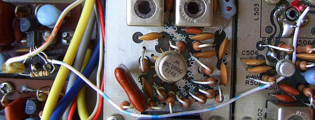
Insulated wire as "antenna" for the marker generator.
|
|
Original 100 kHz oscillator. |
25 kHz markers (fig»). |
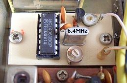
New 6.4 MHz oscillator. |
Due to the 12.5 kHz channel raster it is more convenient to have 12.5 kHz markers. A 4060 IC with cheap 6.4 MHz crystal are suited as oscillator and divider to obtain the required markers. If divide by 512 (pin 13) one gets 12.5 kHz markers, but they are not as strong as a division by 256 (pin 14) for 25 kHz calibration. So the last system was chosen because it is accurate enough to tune on the 12.5 kHz channels. Pen 13 can be used for a 12.8 crystal.
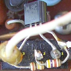
More uniform pulses can be obtained with an additional IC as amplifier or pulse shaper, but a simple general purpose transistor (T) is sufficient. I tested various types and for example BC547 and C945 produce clear signals in the 2 m band. Strangely a BF199 RF transistor gave a much weaker signal in this circuit.
IF FILTER XF301 (10,7 MHz)
A simple and inexpensive method to reduce the IF bandwidth is to replace filter XF301 a 30 kHz wide type. This two crystal ladder filter can be replaced by a narrower type 10F7.5A of NKD. Probably you had considered a 10F15A filter but in practice this type is still too wide. The advantage of such types is that they fits on the original PCB. Only L301 and L302 need adjustment. The bandwidth is sufficient to suppress an adjacent channel. Unfortunately many operators failed to realize that their sweep signal is a bit to wide.
IF FILTER CF301 (455 kHz)
|
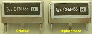
Even ladderfilter CF301 with 9 ceramics elements can be replaced by narrow type such as: |
CFM-455D, ±7kHz/3dB, ±10kHz/6dB, ±20kHz/70dB CFM-455E, ±5.5kHz/3dB, ±8kHz/6dB, ±16kHz/70dB CFM-455F, ±4.2kHz/3dB, ±6kHz/6dB, ±12kHz/70dB CFM-455H, ±3kHz/6dB, ±7.5kHz/70dB |
|
|
|
At input and output filters CFM-455F and CFM-455H should be loaded with 2 kOhm in stead of 1.5 kOhm (R310 and R311).
As a test filter CFM-455D was replaced by CFM-455H but R310 and R311 remained unchanged. It worked as well without any further adjustment, so it was not removed. In a second FT-220 R310 and R311 were replaced by 2.2 kOhm.
When installing a narrower 455 kHz filter (CF-301), it is not absolutely necessary to replace the 10.7 MHz filter (XF301).
LOCAL OSCILLATOR PB-1348A
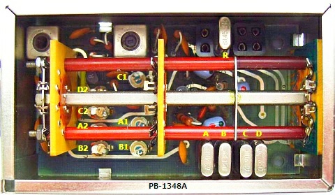
In many FT-220's (export Europe) is a PB-1348A "Local Oscillator" is installed instead of PB-1418. Furthermore, the numbering of trimmers in the schematic are not the same as the numbering on the PCB. A adjustment can produce wrong results. In table and image I have pictured right relationship of trimmers and 2 m band segments.
The system is a 62 - 63 MHz local oscillator followed by an amplifier as doubler. For band D (145.5) only a solid 10 pF capacitor is used.
Frequency adjustments is done with trimmers A1 - C1 and doubler stage (output) with trimmers A2 - D2. Trimmer C1 for band C (145.0) is also used for repeater shift crystal. Therefore repeater reception frequency may vary slightly but (according to the manual) correction is possible with the "Clarifier".
BRIDGE RECTIFIER
|
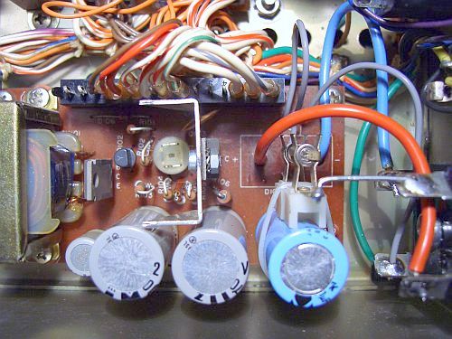
Original bridge rectifier. |
Screw this board firmly to avoid 50 Hz hum. |
|
|
Extra "coolers". |
Stations repeatedly reported that my signal was disturbed by hum. At first the aged electrolytic caps were suspecious and indeed one had to be replaced. Unfortunately hum remained and a lengthy search began. In the end, it turned out to be the attachment of the power supply PCB. Firmly screwing the four screws resolved the problem. For additional security copper on the PCB and surface around threaded holes on base cover were cleaned. With this procedure the hum was cured in a second FT-220!
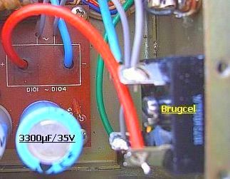
The bridge rectifier (D101 - D104) of the power supply is cooled by two metal strips each installed with two diodes. If diodes are heated-up fingers are burned if you touch them. It has surprised me that diodes still do their job. To be sure, they were replaced by a bridge rectifier block mounted at the back plate in the place of C10 (3300 µF/25 V), wich was removed.
To compensate for the loss of capacity C101 (1000 µF/25 V) was removed and replaced by a smaller present-day's 3300 µ/35 V and C22 (1000 µF/25 V) parallel to transistor Q1 ( 2SD114) was also replaced by the same present-day's type.
In my opinion the bridge rectifier block and Q1 were getting too hot during FM transmission. Assembling two heat sinks at the back cover fixed the cooling. Transistor Q1 on the power supply board was provided with U-shaped section strip for extra cooling.
DIAL ILLUMINATION
When my used set was purchased, two lamps of the dial scale illumination were missing. In order to prolong lamp's service life I always supplies with a constant current source or use a 18 Volts type in stead of 12 V, because often light intensity is too bright
In this FT-220 two 12 V/4 W car dashboard types were installed. If supplied with a 8 V regulator they illuminate a lifetime without blinking during transmission. More over the temperature of the dial lamp is cool is enough not to melt the plastic of the dial drum. Make sure that the lamp does not touch the drum!
Today it might be more convenient to mount LED's.
TB76001 MODIFICATION
Probably not many FT-220 owners are aware of YAESU's technical bulletin TB76001 for 20 dB improvement of cross modulation characteristics. That's not a bad idea because the original noise blanker is driven directly by the RF/MIX unit. With the modification the noise blanker gets its signal via an 10.7 MHz IF filter.
Due to the scant bulletin it is not possible to check whether it is an official YAESU publication but I have the information collected in (fig») an image.
As it is described and then compared with FT-220's schematic, the connection between pin (6) of PB1357A and pin (1) of PB-1302A is cutted. So the FM/IF unit will not get drive from the RF/MX unit and FM receiver section would not work. Since this finding has not been compared with the actual wiring, I did not (yet) applied the modification.
![]()
![]()